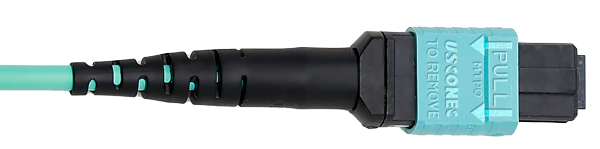
Male Connector
WITH Guide Pins
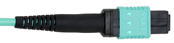
Female Connector
WITHOUT Guide Pins


Today, the utilization of MPO/MTP® cables plays a crucial role in facilitating high-speed data transfers by enabling the efficient inter and intra connections between Data Storage and Distribution Points. As the demand for larger data transfer escalates due to the rapid proliferation of cloud computing, IoT, and AI applications, the prevalence of network infrastructures employing MPO/MTP® cables is set to grow significantly in the upcoming years. In order to achieve optimal results when installing and using these cables in a network environment, it is essential to possess fundamental knowledge about cable attributes and specifications. This article aims to equip readers with the necessary know-how to accurately identify the appropriate application and location for a specific cable.
The standard and the improved
The differentiating factor between MPO and MTP® fiber optic cables resides in their connectors. With its advanced design, MTP® connectors offer superior mechanical characteristics and optical performance compared to MPO cables. These distinguishing features break down as follows:
MPO stands for ‘Multi-fiber Push On.’ MPO connectors are the generic model upon which MTP connectors are based. Here are the defining features and benefits of MPO cables:
MTP® is a brand name for the MPO connector developed and manufactured by US Conec Ltd. Here are the key differentiators and benefits of MTP cables:
Male or Female
When working with MTP®/MPO connectors, “gender” is a term used to differentiate between connectors. This helps to navigate cables and ensure the correct connector is used for a task. A firm connection is vital in aligning fiber endpoints, achieved by having guide pins on one side and receptors on the other. By being aware of these details, potential issues can be avoided and systems run smoothly.
WITH Guide Pins
WITHOUT Guide Pins
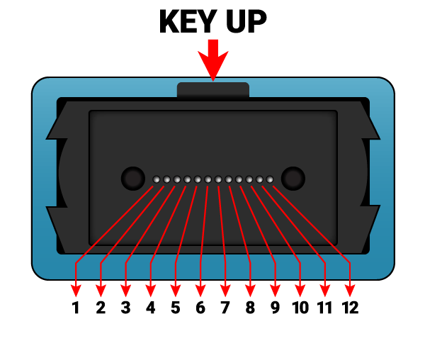
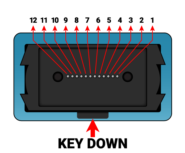
Key Positions
The key position on the connector is a mechanic feature that guarantees the correct orientation of the connector as when plugging into a receptor. A connector can be either KEY UP or KEY DOWN and the position of the key plays two important roles:
When specifying a fiber in a connection, it is important to indicate the position of the key. The numbering of each strand corresponds to its connection in the connector. It is standard practice to assign sequential numbers to strands starting from the left to right side of the key. To illustrate this numbering system, examples are shown in the images below for an MPO-12 with key-up and key-down configurations.
Method A, B, & C
An optical link needs a pair of optical fibers to transmit signals. The optical module comprises a transmitting end (Tx) and a receiving end (Rx). Proper interconnection between the two ends is needed, which is called polarity. Polarity indicates the direction of optical signal movement in the fiber, and it is essential for matched transmitting and receiving ends. TIA 568 standard defines three methods for correct polarity, referred to as Method A, Method B, and Method C. Three types of MTP fibers, namely Type A, Type B, and Type C, are used to match the three different connectivity methods in compliance with these guidelines.
Color Guided Cable Ratings
MTP® and MPO cable jackets are color coded so that you can easily differentiate between them. The color corresponds with an industry standard rating for specifications of the fiber utilized in the cable. For example, the yellow jacket means the cable has a single-mode fiber and the Aqua Jacket means it has a multimode fiber. The color table below is a quick reference guide showing which cable category belongs to each color to make things easier.
| Optical Fiber | Category | Jacket Color | |
|---|---|---|---|
|
Single Mode |
OS1 / OS2 |
Yellow |
|
|
Multi Mode |
OM3 / OM4 |
Aqua |
|
|
OM5 |
Lime Green |
|
|
Trunk & Breakout Cable Connections
Trunk cables offer superior transmission performance and high density with minimal signal loss. These cables enable 1:1 connections where both endpoints have matching speeds, ensuring that data input on one end matches that on the other end.
The chart provided below details the correlation between transceiver transmission and receiving lane count with the required fiber count of the cable. Short abbreviations denoting Short Range (SR) and Long Range (LR) transceivers have been utilized. Following either SR or LR, a numerical value has been included representing the number of transmission (Tx) lanes and receiving (Rx) lanes respectively.
| Optical Fiber | Transceiver Tx Lanes | Fiber Count | Typical Data Rate |
|---|---|---|---|
|
Multi Mode |
SR4 |
12 |
40G, 100G |
|
SR8 |
16 |
200G, 400G |
|
|
CFP/CFP2/CPAK SR10 CXP SR12 |
24 |
100G |
|
|
SR16 |
32 |
800G |
|
|
Single Mode (PSM4) |
LR4 |
8 |
40G, 100G |
|
LR8 |
16 |
200G, 400G, 800G |
MPO Break-out cables are a highly effective way to split and combine data flow. One of the most common types of break-out cables is the MPO to 4 LC. Additionally, the 1 to 4 conversion is ideal for converting from 40G to 4x10G and from 100G to 4x25G, as both use the same MPO breakout cable. However, it is important to note that not all 40G and 100G transceivers can handle this conversion, as it requires a built-in MPO connector and is only available in the SR4 and PSM4 transceiver versions, which are both short-range 4-lane interfaces.
The trend of using 1 to 8 break-out conversion is gaining popularity. This involves the use of a 200G SR8 or 400G SR8 at one end and a 25G SFP28 or 50G PAM SFP56 at the other end, to match the data rate. This method simplifies the topology and reduces the number of equipment required for conversion from high to low data rate.
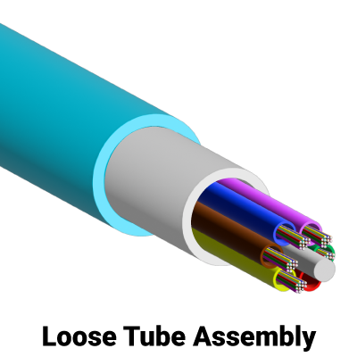
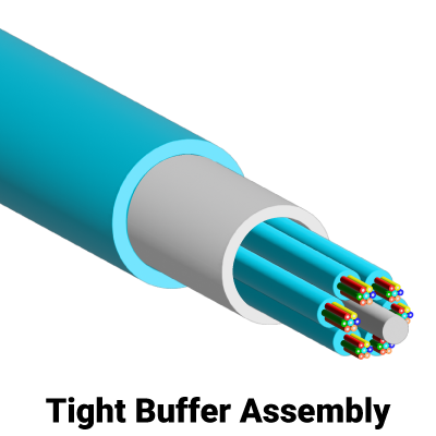
Loose Tube vs Tight Buffer
There are two major forms of fiber optic cables: Loose Tube and Tight Buffered cable. While both cables have a dielectric central member and strength member, they are designed for different surroundings. Understanding the differences between the two types of cables is essential in identifying the appropriate choice for your specific needs.
A loose tube cable comprises 250μm fiber core and is bundled within a semi-rigid protective tube or sleeve. To protect the fibers against external forces, one to 12 fibers are insulated in individual water-blocked buffer tubes. These tubes are usually stranded around a fiberglass central strength member for more sturdiness and strength. Loose tube cables can support up to 432 fibers within the tubes and are made either in dry-block or gel-filled constructions.
Loose tube cable is versatile. It offers an optional water-resistant gel surrounding the fibers making the cable ideal for harsh, high-humidity environments where water or condensation can be a problem. The gel-filled tubes can expand and contract with temperature changes, too. Loose Tube cables can be used for outdoor installation and various applications such as LAN, MAN, WAN, telecommunications, data center, and ethernet.
Tight buffered cable design ensures excellent protection against environmental and mechanical damage using a 900μm buffered fiber surrounded by a water-resistant, dielectric strength member. The fiber is then covered by a flame-retardant outer jacket, which is either flexible or rugged polyurethane. Tight-buffered fiber cables can have fiber counts ranging from 1 to 144, but usually, cables with 2, 6, 12, or 24 fibers are most commonly used. For specific applications, fiber counts of 48, 96, and 144 are also available.
Tight buffered cable durability and reliability make it an ideal choice for use in intra-building data centers, backbones, patch cords, equipment cables, LAN, WAN, Storage area network (SAN), and long indoor runs. Additionally, tight buffered cable is easier to install than the loose tube cable because there is no gel to clean up and it does not require a fan-out kit for splicing or termination.