Optical Attenuation Reference Guide

"Look Before You Leap"

This guide outlines general best-practice guidelines for optical attenuation. Actual attenuation requirements will vary depending on the specific transmitter output power and receiver sensitivity of the optical modules in use.

Note: The values presented are approximate and provided for reference only. Optical power levels should always be verified—either with an optical power meter or by reviewing transceiver Rx power readings—to ensure they fall within the specified safe operating (dynamic) range of the transceiver prior to final connection.

The "Rule of Thumb" for Loss

Use the following conversion as a baseline for estimating distance loss, but treat it as a starting point only. Because specifications vary, you must always verify these estimates against the actual Rx power readings of your optic in the field.

  • 1310 nm Wavelength: 1 dB Attenuator is about 3 km of distance loss
  • 1550 nm Wavelength: 1 dB Attenuator is about 5 km of distance loss
Distance (Fiber Span)
40km Optic (1310nm)
40km Optic (1550nm)
80km Optic (1310nm)
80km Optic (1550nm)
≤ 5 km
10 dB
7 dB
Not Recommended
Not Recommended
5km ~ 10km
8 dB
5 dB​
10 dB
12 dB
10km ~ 15km
6 dB
4 dB
8 dB
11 dB
15km ~ 20km
5 dB
3 dB
7 dB
10 dB
20km ~ 30km
3 dB
-
5 dB
10 dB
30km ~ 40km
-
-
2 dB
8 dB
40km ~ 50km
-
-
-
5 dB

⚠️ IMPORTANT WARNING FOR LONG-REACH OPTICS

  • 40 km transceivers – Do Not Test or Use with ≤ 25 km fiber cables
  • 80 km transceivers – Do Not Test or Use with ≤ 60 km fiber cables

Long-reach transceivers have highly sensitive receivers.

Do not run initial tests on ER or ZR optics using short fiber lengths.  Connecting them directly to equipment or using short cables without proper attenuation can:

How to Protect Your Optic

Optical Power Budget

What Is an Optical Power Budget?

Think of it like a fuel gauge for light. Every fiber link has a finite amount of optical power — the power budget tells you how much you have to spend after accounting for all losses along the way.

If the budget is positive, the link works. If it goes negative, your receiver won’t see enough light — and the link fails.

The formula on this page lets you calculate that budget for any transceiver and fiber run — before anything gets installed.The formula on this page lets you calculate that budget for any transceiver and fiber run — before anything gets installed.

Don’t Use Every Last dB

Always leave margin for real-world losses like dirty connectors, patch panels, fiber bends, repairs, and aging optics.

Rule of thumb: Aim for 3 dB of spare margin after all calculated losses.

If the final budget is close to zero, the link may flap, show errors, or fail later — even if it links up today.

THE FORMULA

Pbudget = PTx − Lconn − Lsplices − Lcable − SRx

VariableTypical ValueWhat It Means
PTxSee datasheetMinimum transmit power (dBm) — worst-case output over the transceiver’s rated life. Use the minimum, not the typical.
Lconn0.25 dB / connectorLoss from each physical connector (LC, SC, etc.). Count every mated pair — each end of a patch cord is one connector.
Lsplices0.3 dB / spliceLoss from fusion splices in the fiber run. Longer outside plant runs typically have more splices at each cable junction.
LcableSee table belowAttenuation from the fiber itself — depends on wavelength and cable length. Multiply dB/km by distance in km.
SRxSee datasheetWorst-case receiver sensitivity (dBm) — the minimum signal the receiver needs to work reliably. More negative = more sensitive = better.

Fiber Attenuation by Wavelength

Worked Example: SFP-10G-ZR (1550 nm)

WindowWavelengthLoss / km
1st850 nm~3.0 dB/km
2nd1310 nm~0.4 dB/km
3rd1550 nm~0.25 dB/km
4th1625 nm~0.25 dB/km

If Pᵇᵘᵈᶟᵉᵗ is negative, increase margin or shorten the span.

Min. Tx Power (from datasheet)

0 dBm

Rx Sensitivity (from datasheet)

-

(−24 dBm)

Raw Power Margin

=

24 dB

Connector Loss (2 × 0.25 dB)

-

0.5 dB

Safety Margin (industry standard)

-

3 dB

Available for Cable

=

20.5 dB

1550 nm fiber attenuation

÷

0.25 dB/km

Maximum Reach

=

82 km

This is why the SFP-10G-ZR is rated at 80 km — manufacturers apply a standard 3 dB safety margin.

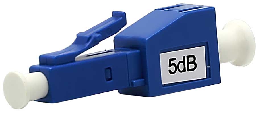
Watch the Other End Too

Too close can also be a problem. If received power exceeds the receiver’s maximum, the link can overload and fail.Check Max Tx Power and Max Rx Power from the datasheet. Very short links may need an in-line attenuator.